Myst(ery) Box
I’ve made a mystery box for my girlfriend’s birthday present, powered by Arduino, two servos, a handful of phototransistors and a bunch of LEDs. (Source code link near the bottom.)
My girlfriend and I have been playing Myst a lot lately.
These games are old, but real classics. You’re the “stranger,” visiting different worlds (called “ages”) that are full of intricate mechanical and logical puzzles for you to solve. There’s no time pressure; no way to actually lose except by giving up. It’s hard not to get lost in the story that’s unfolding around you, or in the breathtaking environments where it all takes place.
Anyway. My girlfriend’s birthday was coming up, as it is prone to at this time of the year. I needed a present. And then, I needed a delivery mechanism for the present.
And since the present turned out to be representable by a rather smallish token, I thought I could conceivably build some kind of Arduino-powered device around it.
And that’s where Myst comes in.
Myst puzzles often work like this: You’ve got a device in front of you and no idea how to use it. If you’re lucky, there are some clues in one of the various papers or personal diaries you’ve found earlier. The device invariably includes at least one button or lever of sorts, and usually something moves or lights up when you do something right (or wrong).
So I built something like that over the past two weeks. Here it is:
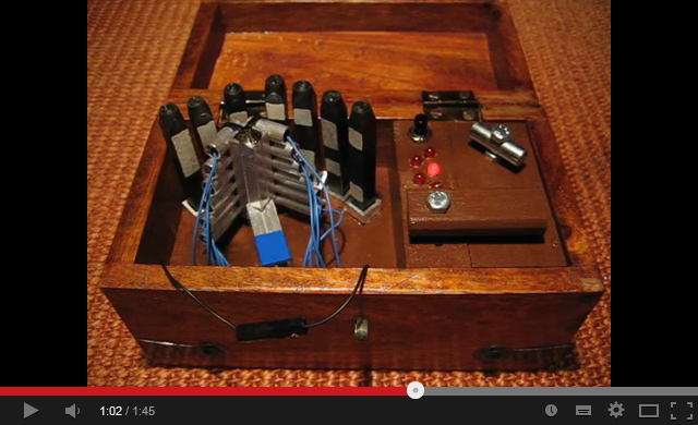
(I didn’t make the wooden box, of course. Just its innards.)
The markings on the rods are binary numbers: white is 1, dark is 0, read from top to bottom. Each rod that is placed correctly moves the latch by one step; each rod that is part of the correct code, but not at the right place, makes the latch twitch once. With a bit of patience, it’s possible to logically deduce the correct subset and order of the rods for the latch to open completely.
Some technical notes:
-
The whole thing is powered by a 9 V battery connected to Arduino’s GND and Vin pins. The socket-and-plug thingy shown at 0:19 in the video physically connects the GND line between the board and the battery. (If I’d had more time, I’d have made a little circuit to cut power from the entire device when inactive, but looking back, the idea of first having to “power up” the machine before being able to use it is really very Myst-like.)
-
Everything past the Arduino, including the servos, is fed from its 5 V output pin. That’s not terribly efficient, battery-wise, but it makes everything’s performance more consistent.
-
The LEDs on the panel and the LEDs in the scanner device are pairwise connected in series with a 20 Ω resistor, which makes them run at 25 mA instead of the 20 mA they’re rated for. Their datasheet says they can sustain that current, and I hope they might be ever-so-slightly brighter for it.
-
The scanner device is made from aluminum and provides common ground for the scanner’s LEDs and its phototransistors (that’s why there is only one cable coming from each of the sideways tubes).
-
Each phototransistor (in the right-hand tubes of the scanner device) is connected through a 5 kΩ series resistor to Arduino’s 5 V pin, and the voltage at each point between the phototransistor and the resistor is fed into one of Arduino’s analog inputs. (This means that “dark” corresponds to a voltage around Vcc, and “bright” makes it go down to lower voltages.)
-
The phototransistors turn out to be incredibly directional. Even under bright environmental lighting conditions, they’re only really affected by light coming in from straight ahead.
-
Getting consistent high/low readings from the phototransistors was a major headscratcher. I ended up using the difference between a lit and an unlit measurement and comparing it to a per-sensor and per-position threshold.
-
You may have noticed that the scanner device overswings slightly when going past the middle, then returns to its intended position. That’s because the servo often starts grumbling when moving away from its neutral position (which is in the middle) in this setup, presumably because there’s some slight mechanical counter-force that prevents it from ever reaching its desired position. Moving slightly towards the middle at the end of the movement works around that issue.
-
You may also have noticed that the scanner does three distinct measurements at three slightly varying angles. That’s to work around that fact that the marked metal rods just aren’t as neatly (and consistently) aligned to the sensors as I had imagined them to be. The software uses the “brightest” response from the three measurements. (Getting no response is not usually a problem.)
-
I also know now why digital servos exist. (Those analog servos’ movements are only consistent to within approximately 1°, it appears. Even more reason to make several measurements at different angles.)
-
The servos’ movement, in general, is mediated by an interpolation routine that uses an easing curve designed in Inkscape. (The “overswing” movement and the latch’s “twitch” movement are just special cases of that.) The only time you see a servo move at its native speed in the video is when the device is powered up (at 0:24).
-
Everything in the software is synchronous – except for the LEDs’ “idle” animation, which uses my non-blocking Timer library so it can be interrupted at any time.
Here’s the Myst Box source code repository.
Putting this all together was a lot of fun – mingled, of course, with the requisite brief moments of frustration, exasperation, exhaustion, occasional feelings of being overwhelmed by the sheer amount of little things to think about, and the few exclamations of “WTF” that seem to be part of any such project.
Let’s hope she’ll have as much fun solving it. (The present, by the way, is a trip to GC319QK.)
Happy birthday!