Prelude to a bus
I want to attach all my Arduino peripherals to a single I²C bus, and it turns out that one of my sensors needs to get its own ATtiny45 brain to make that work.
My current Arduino project needs quite a few peripherals:
- a knock detector,
- a whole bunch of electromechanical sensors (switches) and actors (magnets),
- a 10-position binary code switch,
- and an audio shield.
The audio shield is important here because it occupies a whole nine out of Arduino Uno’s twenty general-purpose input/output (GPIO) pins, including four of the six available “analog in” pins. (And six more digital inputs for its “multifunction button”, but that only matters if you intend to actually use it.) There still remain a few pins for other uses, but certainly not enough for all those components listed above.
In addition, in my project’s setup, most peripherals are located an arm’s length away from the Arduino. Even if I could conjure up more GPIO ports on my Arduino board, I’d rather avoid stringing dozens of individual signal cables across my entire installation.
So, clearly, what I want is some sort of data bus.
I’ve read plenty about the disadvantages of using I²C for long-distance communications – notably that it was never intended, let alone designed, for that kind of use. All it was designed for is inter-IC communication over traces on a PCB, not meters of dangling cable.
But I don’t need anywhere near that much distance. I also don’t require any bandwidth to speak of.
And I²C seems just so very convenient. I can’t resist giving it a try.
The ATmega328 microprocessor that’s on my Arduino Uno board has built-in I²C hardware support and there’s Arduino’s standard Wire library that promises to make it easy to use an Arduino as an I²C master, slave, or even both (which may require a bit of tweaking, perhaps).
Those mechanical sensors and actors and the binary code switch lend themselves to taking a passive role – it’s the Arduino that wants to actively check a switch, activate a magnet, or query the position of the code switch at some point. So I’ve bought a handful of I²C port expanders that effectively work like remote-controllable open-drain I/O ports. They’re pretty simple in what they do, but that also means that they are very easy to use.
That leaves… the knock detector.
The core of the knock detector is a piezoelectric sensor – a piece of material that generates voltage (but not much current) when pressed or bent. To detect a knock, I have to watch for a voltage spike in the piezo’s output. The amplitude of that spike is strongly dependent on the amount of pressure exerted on the piezo – anything in the range of a few millivolts (have the sensor lie flat on the table, and knock against the table) and dozens of volts (tap directly on the sensor). Its duration is somewhere in the range of milliseconds.
With a few additional components (a pair of diodes, an analog comparator, a trimmer), I can make the piezo’s analog output into a tunable digital one (active-low when above a given threshold, high/floating otherwise):
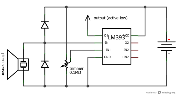
(You can probably tell I’m new to this.)
I could attach that output to one of those I²C port expanders and have the Arduino poll it. Those voltage spikes are rather short, so I’d have to poll really frequently, or I’ll probably miss most of them.
And that, well, that just doesn’t seem like a very good idea. Swamping the I²C bus with hundreds of identical read requests per second, almost all of them returning nothing at all, is just so resoundingly brutish and ugly that I’ll leave it to someone who actually has no other choice. At all.
So. What’s the plan, then?
The knock detector needs to locally monitor the piezo voltage; actively push information about knock events to the Arduino; and possibly even send locally-gathered timing information along, which also makes it possible for it to locally buffer detected knock events just in case it can’t get detected events to the Arduino as fast as they occur.
Unless somebody unearthes some ready-made knock detection IC somewhere, this calls for a dedicated microprocessor. (Finally a reason to get my hands dirty with an AVR without the training wheels. Yay!)
So, today, I’ve ordered a handful of ATtiny45s. My brand-new AVRISP mkII programmer is already sitting next to me on my desk.
The ATtiny45 is physically small (even if I stick to the DIP form factor – soldering SMD by hand is still black magic to me), and it doesn’t make me feel like three quarters of the pins are going to waste. It’s juuust big enough for this task. In addition, the ATtiny25/45/85 models all have built-in hardware support for I²C by means of their “Universal Serial Interface” (USI) module.
And it’s cheap: I’ve ordered mine for less than an Euro per unit.
Here’s the pinout, straight from the datasheet:
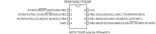
Huh. That’s what you get when you have so very few pins: massive, massive overloading.
Let’s brainstorm. What are my options?
- Use two diodes and an analog comparator (see above) to externally digitize the piezo’s output. Feed that into PB1, PB3 or PB4.
Use SDA and SCL (alias PB0 and PB2) for I²C communications, taking advantage of the USI hardware, which talks through these pins.
- Pros: Can use USI for I²C and the PCINT0 interrupt for knocks.
- Cons: Need an external analog comparator and two clipping diodes.
- Feed the piezo output directly into the internal analog comparator behind AIN0 and AIN1 (alias PB0 and PB1),
exploiting an AVR’s internal clipping diodes.
Talk I²C through, well, two other pins because AIN0 and SDA are both mapped to PB0, so I can’t use USI.
- Pros: No external components, and can use the ANA_COMP interrupt for knocks.
- Cons: Need to bit-bang I²C.
- Directly attach the piezo to PB1, PB3 or PB4, still exploiting the internal clipping diodes.
Use the internal ADC to read analog voltages. Implement the threshold in software.
Use SDA and SCL for I²C.
- Pros: No external components, and can use USI for I²C.
- Cons: No interrupt for knocks.
All three cases support the use of an external trimmer to adjust the knock detection voltage threshold – either attached to the analog comparator’s other input or, in the third case, to a second ADC pin.
The first two options absolutely require a trimmer (or a fixed voltage divider) to supply a reference voltage to the analog comparator, external or internal.
The third one is different in that it implements the threshold in software, so here’s a crazy idea: Instead of using a mechanical trimmer, I could code up an I²C-triggerable “training mode” where the knock detector just listens for a while, gathering some sensor statistics (like baseline noise and absolute maximum amplitude), and then uses those to configure itself.
Hmm.
I currently tend towards the third option including that fancy training mode thingy, so I guess I’ll try that first. Let’s see how much of that functionality I’ll actually be able to squeeze into my ATtiny45 when it’s here…